Power Transformer Tanks
Complete welded steel tanks for oil-filled transformers, from distribution class to large power ratings.
- Rating range
- Distribution class to power class, in MVA (see table below)
- Tank construction
- Corrugated · plain wall · conventional · bell-type
- Material
- Structural steel plate; non-magnetic stainless where specified
- Welding
- MAG / MIG / TIG; submerged arc on long seams
Overview
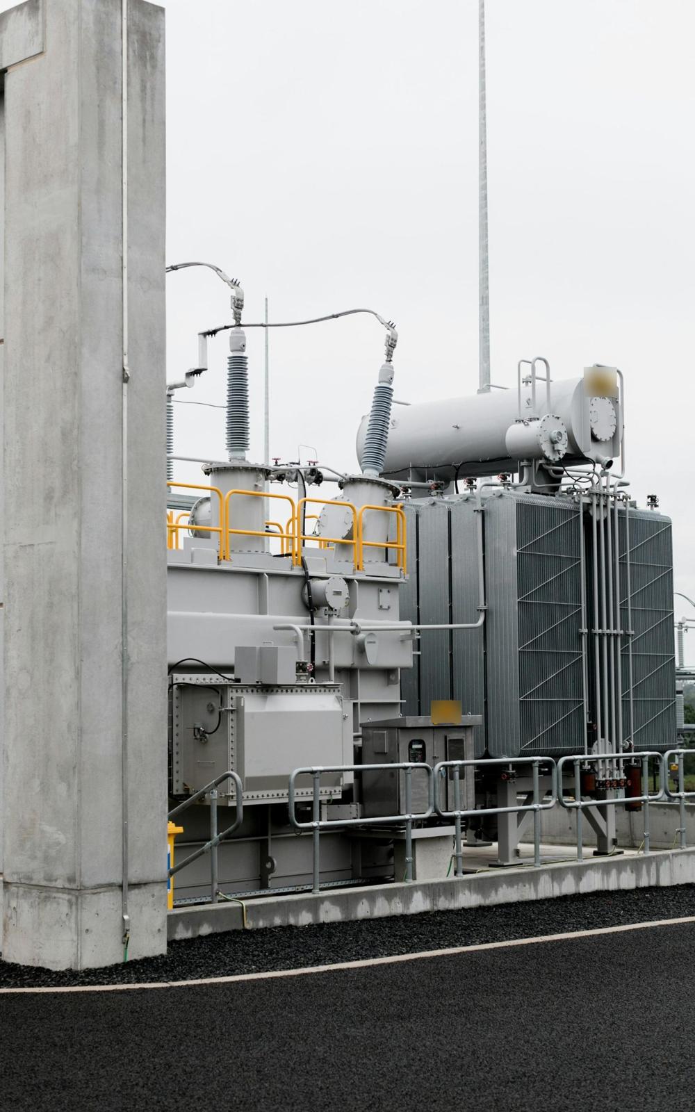
We manufacture complete transformer tanks across the full MVA range: corrugated and radiator-type tanks for distribution transformers, and conventional or bell-type tanks for substation and generator step-up power transformers. Each tank is cut, formed and welded from steel plate with its stiffeners, flanges, radiator connections, lifting lugs and fittings, built to the transformer maker's drawings. Every tank is leak, pressure and vacuum tested before painting and dispatch.
Our capabilities
- 01Complete tanks: main tank, cover and base
- 02Corrugated fin-wall, radiator-type and bell-type tanks
- 03Sealed and conservator-type designs
- 04Radiator banks and cooler headers
- 05Conservators, bushing turrets, cable boxes and headers
- 06Magnetic shunts and tank shielding fitted to drawing
- 07Stiffeners, lifting, jacking and haulage lugs
- 08Leak, pressure, vacuum and insulation testing
- 09Shot blasting to Sa 2½ and multi-coat paint systems
Tank designs by rating
Rating bands follow common practice under IS 2026 / IEC 60076. The tank style is set by the transformer designer; these are the constructions we typically build in each band.
Distribution class
Corrugated fin-wall or plain tanks with pressed-steel radiators for distribution transformers to IS 1180. Hermetically sealed or with conservator. Pole-mounted and ground-mounted designs.
Medium power
Conventional rectangular tanks with detachable radiator banks, conservator and bushing turrets, for ONAN / ONAF cooled substation transformers.
Large power
Conventional or bell-type tanks designed for full vacuum, with cooler banks, magnetic shunts or shielding and transport-profile limits.
Furnace, rectifier & reactor
Heavy-duty and non-standard tanks for furnace, rectifier and traction transformers and for shunt reactors.
Testing & inspection
Every power transformer tank is tested to an agreed inspection and test plan (ITP) before it leaves the plant. Customer and third-party inspectors are welcome to witness.
Leak tightness
Air pressure test with soap-bubble check on all welds, and kerosene–chalk or oil leak test on seams, flanges and gasket faces.
Vacuum withstand
Full or specified vacuum held for the agreed duration, with permanent deflection measured on tank walls and cover.
Pressure withstand
Over-pressure test to the transformer maker's specification, with deflection readings recorded at defined points.
Insulation resistance
Megger (IR) test of insulated core clamps, magnetic shunts and frame parts, plus earthing continuity checks between tank, cover and fittings.
Weld NDT
Visual weld inspection on 100% of seams, with dye penetrant (DPT), magnetic particle (MPI) or ultrasonic (UT) testing on critical joints.
Dimensional & fit-up
Flange flatness, bushing turret and valve positions, cover fit and trial assembly of radiators and conservator against the general arrangement drawing.
Surface & paint
Shot blasting to Sa 2½ (ISO 8501-1), dry film thickness (DFT) readings and cross-cut adhesion test on the finished paint system.
Documentation
Test certificates, mill test certificates (EN 10204 3.1), WPS, PQR and welder qualifications, and a final dossier with every tank.
Technical data
| Rating range | Distribution class to power class, in MVA (see table below) |
|---|---|
| Tank construction | Corrugated · plain wall · conventional · bell-type |
| Material | Structural steel plate; non-magnetic stainless where specified |
| Welding | MAG / MIG / TIG; submerged arc on long seams |
| Testing | Leak · pressure · vacuum · weld NDT · insulation resistance |
| Surface preparation | Shot blast to Sa 2½ (ISO 8501-1) |
| Paint system | Epoxy primer and polyurethane top coat; oil-resistant interior coat |
| Documentation | ITP · EN 10204 3.1 MTC · WPS / PQR · test certificates |
Values reflect common industry practice and referenced standards. Final values are set by your drawings and specification.
Our project approach
- 01
Submit drawings & specs
Send your drawings, specifications and quantities. DXF, DWG, STEP or PDF.
- 02
Proposal
A clear technical and commercial proposal with price, scope and delivery date.
- 03
Manufacturing
Fabrication, finishing and inspection to the agreed quality plan.
- 04
Dispatch & site support
Packed and dispatched by road across India or crated for export, with erection and commissioning support at site.
FAQs
Where are the parts made?
At our own plant in GIDC Makarpura, Vadodara, Gujarat. Engineering, the tool room, fabrication, machining, finishing and testing all happen on the same site.
Who do I deal with?
Our engineering team is your single point of contact, from quote to delivery and after-sales service.
What files do you accept?
DXF, DWG, STEP and PDF drawings. We can also work from sketches or samples through our design service.
Can we inspect parts before dispatch?
Yes. Your inspectors or a third-party inspection agency are welcome at the plant for stage and final inspection.
What are typical lead times?
Lead time depends on the part, quantity and material availability. Every quote states a firm delivery date.
Request a quote
Send your drawings and specifications. Our engineers will reply with a detailed proposal.